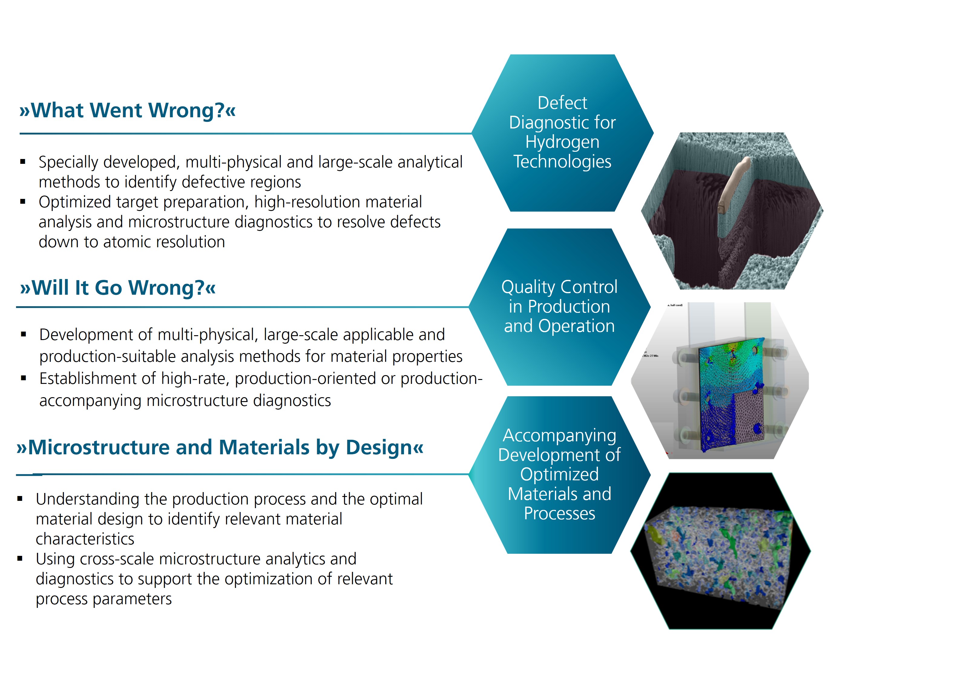
Material Diagnostics for H2 Technologies

Overview of Competences of the group “Materials Diagnostics  for Hydrogen Technologies” at Fraunhofer IMWS
© Fraunhofer CSP
Competences of the group “Materials Diagnostics for Hydrogen Technologies” at Fraunhofer IMWS.
PEM-Stack
© Fraunhofer CSP
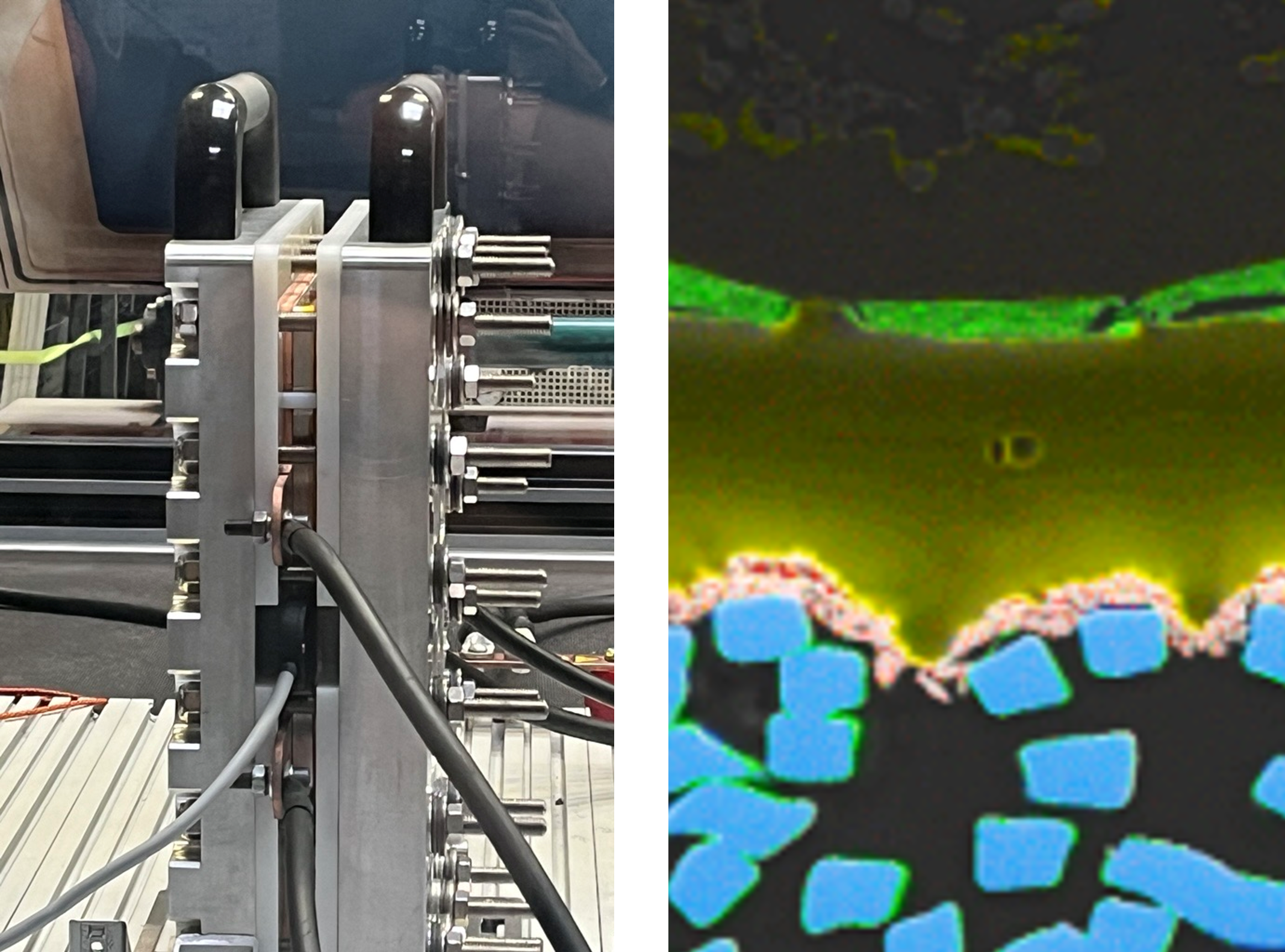
PEM-Stack within FRHY-Project (left) and cross section analysis of a CCM with SEM-EDS (right).

At Fraunhofer IMWS, we are dedicated to advancing hydrogen technologies through comprehensive diagnostics of materials. Our focus lies in understanding the critical interplay between material properties and their performance in applications such as electrolysis and fuel cells. By bridging the gap between theoretical research and practical application, we aim to drive innovation and enhance the quality, efficiency, and sustainability of hydrogen systems.

Key areas of expertise include:

  • Material Characterization: In-depth analysis of material properties and behaviors.
  • Defect Diagnostics: Identification of defects at the micro and nano scale and their avoidance.
  • Quality Control: Ensuring the reliability of materials in production and operation.
  • Optimized Processes: Supporting the development of materials and processes tailored to hydrogen technologies.

We cover expertise for all hydrogen technologies such as

  • PEM: Proton Exchange Membrane electrolysis
  • AEM: Anion Exchange Membrane electrolysis
  • SOEC/SOFC: Solid Oxid Electrolyzer/Fuel Cells
  • AE: Alkaline electrolysis

Further activities:

  • Performance and Reliability: Comprehensive stress and aging tests for material properties under operational conditions.
  • Development of Methods and Measurement Devices: Novel  approaches, setups and devices for advanced sample preparation, spatially resolved electric diagnostics and chemical analysis
  • Prototyping for New Concepts: Manufacturing of functionalized membrane assemblies, e.g. for bubble-free electrolysis
  • Regulatory Compliance & Sustainability: Expertise in navigating regulatory frameworks for Green Hydrogen and Power-to-X, ensuring sustainability criteria for market adaptation.

Our commitment to collaboration and innovation positions us as a trusted partner in the field, ready to meet the specific needs of our partners and contribute to the sustainable advancement of hydrogen technology.

To provide a deeper understanding of our capabilities, we present below a comprehensive overview of the methodologies and analytical techniques we employ in our research and development efforts.

Our Services


Methods for PEM Components

Our Sample Preparation Know-how


Applied H2 Research

Research Infrastructure

Overview of Our Analytical Methods for PEM Technology Components

Schematic of a PEM electrolyzer cell, its components and most suitable analyzation techniques at Fraunhofer CSP/IMWS.
© Fraunhofer CSP
Schematic of a PEM electrolyzer cell, its components and most suitable analyzation techniques at Fraunhofer CSP/IMWS.
Matrix showcasing analytical techniques and their applications across various electrolyzer components.
© Fraunhofer CSP
Matrix showcasing our analytical techniques and their applications across various electrolyzer components.

Stacks of PEM electrolyzers consist of various components, each playing a crucial role in overall performance. Our expertise allows us to provide a comprehensive in-depth analysis tailored to all types and sizes of these components. Whether you need insights at the stack, cell, or individual component level, you can select the specific analyses that will advance your research and enhance your understanding of these systems.


Our most commonly used analysis methods are:

  • Microstructure diagnostics: SEM, FIB, TEM
  • Surface and material analysis: XPS, ToF-SIMS, SEM-EDX, XRF, Raman and IR spectroscopy
  • Electrical characterization: contact resistance, in-plane and through-plane conductivity, Eddy-Current Testing (ECT), MFA
  • Thermal Imaging Techniques: LIT, HV-LIT, VACE-LIT, H2-LIT
  • Material Testing, Accelerated Stress Tests, Aging experiments


Analysis of individual components of a PEM Stack - selection of topics and methods:

  • BPP: Bipolar plates
    • Coating stability: XRF, SEM, Resistance measurements
    • Mechanical testing: Microindentation
    • Points of failure: ECT
  • Gaskets
    • Stress tests, aging experiments
  • PTL: Porous transport layer
    • PTL coatings: SEM-EDX
    • Welding spot quality: cross section
    • Passivation morphology and thickness: resistance measurements, SEM, TEM
  • GDL: Gas diffusion layer
    • Corrosion: XPS, Raman, Thickness
  • Catalysts for the anode (IrO2) and cathode (PtC):
    • Loading determination: XRF
    • Layer thickness and homogeinity: SEM
    • Contaminations: XRF, EDX
    • Microstructure: FIB-SEM, TEM
    • 3D analysis through FIB-slice-and-view
  • Membrane (and pre-components e.g. decal process in CCM production)
    • Membrane degradation and contamination: XPS, FT-IR, ToF-SIMS, SEM
    • Layer thickness, thinning or deformation: LiMi, SEM
    • Pinhole detection: H2-LIT


Stack-Level Analysis

The entire cell stack can be examined with:

  • MFA: Measuring the inner and/or outer magnetic field of the stack to get insights on the homogeneity of the current density distribution
  • XTM and CT as further non-destructive x-ray methods


Cell-Level Analysis (MEA/CCM/Interfaces)

  • MEA: Membrane Electrode Assembly (PTL and GDL remain in place with CCM through clamping or embedding)
  • CCM and individual interfaces

All methods of individual component analysis can be used, additionally suitable are:

  • 3D analysis through FIB-slice-and-view or planar CT/µCT or depth profiles with ToF-SIMS
  • XRF for loading measurements, XTM for inhomogeneities of the layers
  • TEM/STEM for ultra-high resolution diagnostics
  • VACE-LIT, H2-LIT
  • Cross section view for entire MEA


See all availble methods (research infrastructure)


to top

Our Sample Preparation Techniques

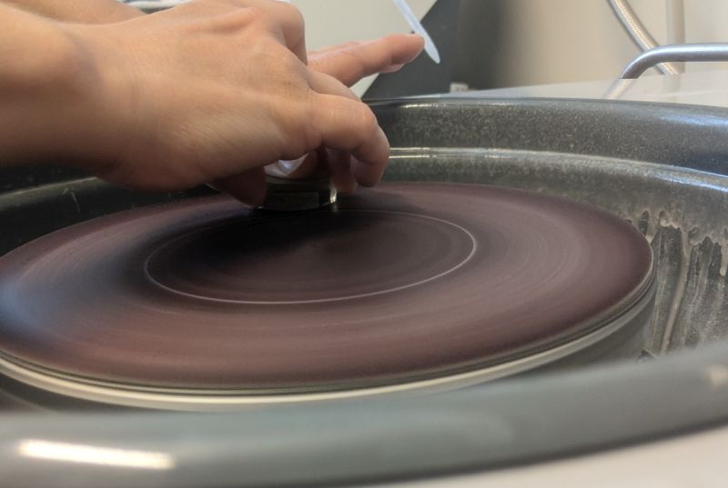
We offer high-quality sample preparations tailored to your needs, including defect localization, careful disassembly, and advanced techniques like laser ablation and FIB-SEM. We focus to preserve sample integrity while providing precise, nanoscale insights for reliable analysis.

  • Tailored analyses and preparation: We offer a complete workflow from defect/peculiarity localization (LIT, XRF, ..) nanoscale sample preparation
  • Separation: Careful disassembly and separation of components through cutting, sawing, and laser processing for manageable samples.
  • Preserving the initial state:
    • Epoxy resin embedding/impregnation preserves spatial consistency for metallographic cross-section preparation (mechanical and ion milling)
    • Cryo-Fracture preparation for membranes and polymers
    • Preparation in inert atmosphere (N2) and transfer to several instruments
  • Finding and analyzing hidden features:
    • Laser ablation processes for selective removal with state-of-the-art femtosecond laser systems (e.g. catalyst layers on membrane) and cross-section preparation
    • FIB-SEM for cross-section preparation in layered systems
  • Insights on the nanoscale
    • Preparation of TEM lamellae with FIB (Ga, O, N, Ar, Xe) in-situ lift out with target preparation at an accuracy down to 100 nm
    • Preparation of high-quality TEM lamellae of soft materials by Ultramicrotomy (e.g. membranes, membrane – catalyst interfaces)
  • Preparation of reference samples
    • Hight quality embedded cross-sections to create reference samples (e.g. calibration of metrology equipment or process control)


    to top

Research Infrastructure – Our Methods and Equipment for H2-Electrolyzer Components

Microstructural Diagnostics

  • SEM: Scanning Electron Microscopy
  • TEM: Transmission Electron Microscopy with high sensitivity EDX
  • FIB: Focused Ion Beam (Ga+ or plasma)
  • XTM: X-Ray transmission microscopy
  • µCT an CT: Computer Tomography with 3D reconstruction
  • SnV: Slice-and-View with FIB-SEM with 3D reconstruction

Material Analytics

  • XRD: X-Ray Diffractometry
  • XRF: X-ray fluorescence
  • EDX: Energy-dispersive X-ray spectroscopy at SEM or TEM
  • XPS: X-Ray Photoelectron Spectroscopy
  • ToF-SIMS: Time of Flight Secondary Ion Mass Spectrometry
  • other MS: Mass Spectroscopy techniques (ICP-MS, GD-MS, GC-MS,…)

 Optical Methods

  • Microscopy (optical, NIR, laser-scanning, 3D, transmission microscopy)
  • Raman: Raman spectrometer (micro- and macro-Raman)
  • FT-IR: Fourier transform infrared spectrometer
  • Height Measurement: Optical profilometer

Electrical Characterization

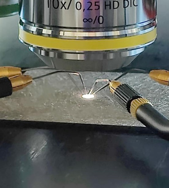
  • Micro probing: Resistivity, I-V curves and 4 point measurements
  • Resistivity under variable force/pressure: In-plane and through-plane
  • TLM: Transfer Length Method for contact resistance determination
  • ECT: Eddy current testing
  • MFA/MFI: Magnetic Field Analysis and Imaging (customizable robotic arm available)
  • EBAC: Electron Beam Absorbed Current Measurement (in SEM)
  • EIS: Electrochemical Impedance Spectroscopy (variable AC frequencies)

Thermal Imaging Techniques

  • LIT: Lock-In Thermography
  • HV-LIT: High-Voltage Lock-In Thermography
  • VACE-LIT: Variable AC frequency Excited Lock-In Thermography
  • H2-LIT: Lock-In Thermography with catalytic heat generation under pulsed H2 application (for sensitive detection of pinholes)

Material Testing, Accelerated Stress Tests, Aging experiments

  • Mechanical Testing (tensile testing, compression set, Young‘s modulus, elongation at break, microindentation)
  • Chemical Testing in autoclaves (variable pressure, temperature, acids for leaching experiments, leaking & transmission rates, ion releases and more)
  • Accelerated Stress Tests, customizable (can including procedures above)

Laser Processing

  • Ultra-short pulse (fs) and short pulse (ns) Laser: for selective laser ablation and high-throughput preparation (possibility for gas analyzation) or sample structuring

See all availble methods


to top

Our Comprehensive Solutions for Your Hydrogen Research Topics

Material Characterization

Defect Diagnostics

Quality Control

Optimized Processes

Performance and Reliability

Regulatory Compliance & Sustainability

Development of Methods and Measurement Devices

Prototyping for New Concepts

Material Characterization

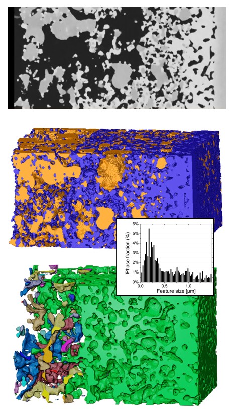
3D Analysis of SOEC Wlectrode in micro and nano scale with FIB Slice-and-View

FIB-SEM Slice-and-view offers a variety of microstructural parameters of your 3D reconstructed sample


Key challenges:

  • Microstructural Analysis Needs: To optimize porous systems, several microstructural parameters must be reliably determined from a 3D model of the sample.
  • Limitations of 2D Imaging: Traditional pure 2D image methods are often insufficient for assessing critical factors.

Our comprehensive service solutions:

  • FIB-SEM Technique: A series of 2D SEM images are acquired using the FIB-SEM slice-and-view technique.
  • 3D Modeling: We can produce a detailed 3D model of your material system - best suited for SOEC samples.
  • Phase Segmentation and Analysis: We provide phase segmentation followed by visualization and calculation of various relevant microstructural parameters, e.g.:
    • Feature Size Distribution from pores and particles
    • Porosity, Dead Volumes, 3D Tortuosity
    • Double and Triple Phase Boundaries
    • and many more
Low and incomplete Pt coverage analyzed with SEM-EDX in top-view configuration
© Fraunhofer CSP
Low and incomplete Pt coverage can be already analyzed with SEM-EDX in top-view configuration.
High quality cross sectional preparation showing incomplete Pt coverage or delaminations
© Fraunhofer CSP
High quality cross sectional preparation of complete MEA can provide even better insights about incomplete Pt coverage or delaminations.

Analyzing PTL Mesh - Finding Failures in Pt Coverage of Ti-PTLs

How homogeneous is the Pt coverage of my Ti-PTL?


Key Challenges:

Insufficient Pt coverage on Ti-PTLs limits functionality in terms of:

  • Contact Resistance: Pt layers on Ti PTLs reduce contact resistance
  • Ti Protection: Pt layers prevent Ti dissolution during operation

Our comprehensive service solutions:

Top view mode:

  • Rapid Screening: SEM-EDX for quick assessment of Pt coverage and uniformity
  • High-Resolution Imaging: Detailed SEM microstructural images for better insights

Cross-Sectional Analysis:

  • Better visualization of detachments and dissolutions of the Pt layer
  • Comprehensive Insights: The influence of the PTLs on the CCM can be investigated in cross sections of complete MEAs
Images genereated through rapid 2D screening with XTM and XRF showing peculiarities in CCMs or MEAs
© Fraunhofer CSP
Rapid 2D screening with XTM and XRF can find peculiarities in CCMs or MEAs. 3D analysis (planar CT or µCT) and high-quality target cross section preparation followed by SEM-EDX analysis can show all the details that are needed for optimizing your process.

From Fast Screening to High-quality Cross Sections

Identifying peculiarities in MEAs for target preparation and detailed analysis


Key Challenges:

Peculiarities in Samples: Fast screening of MEAs or CCMs can reveal unusual features and allowing for the identification of regions of interest (ROIs) to narrow down potential degradation mechanisms and their consequences.


Our comprehensive service solutions:

  • Fast Screening: We provide rapid 2D screening using XTM and XRF to quickly identify areas of interest and propose appropriate further analysis techniques, e.g.:
  • High-Resolution 3D Scans: Advanced 3D high-resolution scans (planar or µCT) to further investigate identified ROIs.
  • Target Preparation: Accurate and high-quality target preparation to visualize selected ROIs in cross-section view.
  • Additional Characterization Methods: We can apply SEM-EDX and other techniques for detailed elemental analysis and microstructural characterization to the cross section of the identified regions. Local in-depth S-TEM analyses can be added.
Cross-section target preparation for identifying irregularities in membrane thickness
© Fraunhofer CSP
From XTM, XRF or other methods to a high-quality cross-section target preparation: identifying irregularities in membrane thickness

High-quality Cross Section Preparation

How can I analyze all layers of a complete MEA for quality assessment?


Key Challenges:

  • Visual peculiarities: Identifying visual irregularities in layer structures
  • Loading Inhomogeneities: Assessing CCM loading inhomogeneities using XRF and XTM
  • Thickness Variations: Measuring variations in membrane and electrode coating thickness
  • Localized Defects: Detecting coating cracks and adhesion differences


Our comprehensive service solutions:

  • Metallographic Cross-Sections: We prepare high-quality cross-sections at selected areas of your embedded MEAs or components (each up to 3 cm wide)
  • Qualitative and Quantitative Characterization: Analyze the structure using light and electron microscopy
  • Advanced Analyses: Additional techniques available such as
    • SEM-EDX for material characterization
    • FIB-SEM, Slice-and-View or TEM lamellae preparation at identified regions of interest
    • and more
Welding Point of an austenitic stainless steel-GDL: optical image and STEM-EDX-Mapping of a Cr-rich phase at a triple point of grain boundaries in the heating zone
© Fraunhofer CSP
Welding Point of an austenitic stainless steel-GDL: optical image and STEM-EDX-Mapping of a Cr-rich phase at a triple point of grain boundaries in the heating zone (HAADF-STEM: High-Angle Annular Dark Field Scanning Transmission Electron Microscopy).

Characterization of Steel Components in PEM Electrolyzers

Are your steel components prone to corrosion and did they corrode during operation?


Key Challenges:

  • Material Usage: Increasing reliance on steels in PTLs and GDLs to manage costs in PEM electrolyzers.
  • Corrosion Issues: Corrosion of steel during operation releases Fe²⁺ ions into the electrolyte.
  • Impact on Membranes: Fe ions catalyze degradation in PFSA membranes, affecting performance.

Our comprehensive service solutions:

  • Corrosion Sensitivity Assessment: We characterize the corrosion sensitivity of end-of-life (EOL) steel components by structure visualization & analysis, also after in-house aging tests
  • Techniques for Corrosion Localization: Optical Microscopy (OM) and Scanning Electron Microscopy (SEM).
  • Advanced Microstructure Analysis: We offer detailed investigation of the microstructure from µm down to sub-nm scale using metallography & SEM, followed by local in-depth analyses by Transmission Electron Microscopy (TEM) and Scanning Transmission Electron Microscopy (STEM) including Energy-Dispersive X-ray Spectroscopy (EDX).


to top

Defect Diagnostics

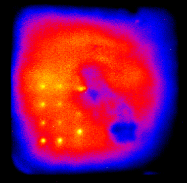
LIT amplitude image showing local reaction of H2 with oxygen from air at laser-inserted pinholes; the holes have diameters in the range of 20-100 µm
© Fraunhofer CSP
LIT amplitude image showing local reaction of H2 with oxygen from air at laser-inserted pinholes; the holes have diameters in the range of 20-100 µm
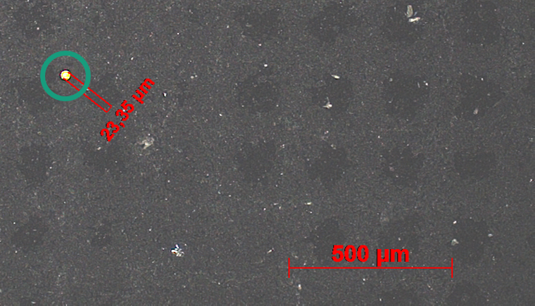
Microscopy image showing one of the pinholes (23 µm) detected with H2-LIT.
© Fraunhofer CSP
Microscopy image showing one of the pinholes (23 µm) detected with H2-LIT.

High-sensitivity Pinhole Detection with H2-LIT

Detecting holes and cracks in electrolyzer membranes by means of Lock-in Thermography


Key Challenges:

  • Gas Crossover Risk: Holes in electrolyzer membranes cause gas crossover, leading to safety issues and potential shutdown of the electrolyzer system.


Our comprehensive service solutions:

  • Advanced Detection: Lock-in Thermography with periodic H2 gas pulsing (H2-LIT) enables the detection of pinholes and cracks in membranes.
  • High Sensitivity: This method allows for the detection of pinholes with diameters below 25 µm, with defect localization achievable within less than one millimeter.
  • Root Cause Investigation: After localizing defects, we utilize various methods in our laboratory to investigate their causes.
  • Design Optimization Support: Our findings assist in optimizing the design of electrolyzers and their components.
Detection of leakage current (40 µA) within a narrow crack of a defective insulator by Lock-in Thermography.
© Fraunhofer CSP
Detection of leakage current (40 µA) within a narrow crack of a defective insulator by Lock-in Thermography.
Current signal in µA range (blue) due to square wave excitation with 800 V (yellow) at 25 Hz.
© Fraunhofer CSP
Current signal in µA range (blue) due to square wave excitation with 800 V (yellow) at 25 Hz.

Electric Current Path Imaging Through Thermography

Precise detection of stray or shunt current paths using most sensitive thermography methods


Key Challenges:

  • Component Degradation: Aging components can lead to unwanted leakage currents in insulators and other areas, posing risks to system reliability.
  • Defect Localization: Effective root-cause analysis and prevention of defects require precise localization of defect sites.


Our comprehensive service solutions:

  • Lock-in Thermography (LIT):
    • Sensitive Imaging: Detects stray current paths with sub-millimeter spatial resolution.
    • Operational Capability: Functional during operation in low/high voltage electric systems.
    • Wide Frequency Range: Effective at frequencies between 0.1 – 100 Hz.
  • Flexible Analysis Options:
    • Laboratory Analysis: Components can be analyzed in our lab setup (up to 10 kV).
    • On-Site Measurements: Conduct measurements at your facility with minimal prerequisites.
    • Requires only periodic voltage variation (any waveform) at frequencies ≤ 100 Hz.
Large area XTM-scan with GDL still attached shows inhomogeneous catalyst coating; XRF assigns this to Iridium.
© Fraunhofer CSP
Large area XTM-scan with GDL still attached shows inhomogeneous catalyst coating; XRF assigns this to Iridium.
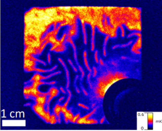
Iron poisoning in XRF: Fe-distribution at a CCM layer after stress test in a H2-electrolyser cell.
© Fraunhofer CSP
Iron poisoning in XRF: Fe-distribution at a CCM layer after stress test in a H2-electrolyser cell.

Fast Screening of CCM & MEA​ with X-Ray Techniques

Does my layer system contains inhomogeneous materials?


Key Challenges:

  • Inhomogeneous Material Distribution: Variability in catalyst layers (e.g., Ir, Pt, contaminants) in Catalyst Coated Membranes (CCMs) can
    • negatively impact performance,
    • create weak spots,
    • cause shorts, and
    • signal reproducibility issues in manufacturing processes.


Our comprehensive service solutions:

  • Non-Destructive X-Ray Screening: Utilizing advanced non-destructive methods, we can rapidly screen various materials for inhomogeneities, such as material agglomerations or depletions at the micron scale using X-ray transmission microscopy (XTM).
  • Elemental Analysis: Our X-ray Fluorescence (XRF) adds elemental analysis to enhance material characterization.
  • High-Resolution Analysis: Localized peculiarities can be further examined using high-resolution techniques like SEM-EDX or S-TEM methods on cross-sectionally prepared samples.
SEM image of a membrane without visible damage, while the ATR-FT-IR spectrum indicates a loss of functional groups.
© Fraunhofer CSP
SEM image of a membrane without visible damage, while the ATR-FT-IR spectrum indicates a loss of functional groups.

Comprehensive Polymer Membrane Degradation Analysis

Is my polymer degraded and decreased in its function?


Key Challenges:

  • Vulnerability to Degradation: Polymer materials are susceptible to chemical degradation processes and poisoning.
  • Diagnostic Limitations: Access to the material is often hindered by catalyst layers, and degradation can occur during measurement.


Our comprehensive service solutions:

  • Multimodal Degradation Diagnostics: We utilize advanced techniques, which are sensitive to polymer chemistry and poisoning agents, such as
    • SEM-EDX
    • TEM
    • FT-IR
    • Raman Spectroscopy
    • ToF-SIMS
  • Flexible Analysis Options: Membranes can be analyzed in cross-section or made accessible through laser processing


to top

Quality Control


Catalyst Loading Determination and Control


What is my catalyst loading and its variability?


Key Challenges:

  • Cost and Functionality: Catalyst loadings on CCMs significantly impact both cost and performance.
  • Measurement Accuracy: Accurately determining absolute catalyst loadings can be challenging.
  • Process Stability Indicator: Variability in catalyst loading serves as a crucial indicator for the stability of coating processes.


Our comprehensive service solutions:

  • Absolute Catalyst Loading Determination: We utilize high-temperature reference methods using TGA equipment to determine references for specific sample systems.
  • XRF Screening: Existing calibration provides insights into reproducibility and consistency of catalyst loadings.
  • Advanced Screening: Higher resolution screening is available to identify coating inhomogeneities down to the μm-range within samples.


to top

Optimized Processes

Profiles of Sb-doped Ti-PTLs analyzed by ToF-SIMS show growth of the TiOx surface layer before and after usage.
© Fraunhofer CSP
Profiles of Sb-doped Ti-PTLs analyzed by ToF-SIMS show growth of the TiOx surface layer before and after usage.
ToF-SIMS depth profile: Revealing surface layer structure of contaminants and grown TiOx layer in used Ti-PTL of a PEM cell
© Fraunhofer CSP
ToF-SIMS depth profile: Revealing surface layer structure of contaminants and grown TiOx layer in used Ti-PTL of a PEM cell.

PTL Depth Profiling by ToF-SIMS

How do surface layers degrade and evolve during use


Key Challenges:

In PEM electrolysis, issues at the surfaces of PTLs include:

  • Formation of TiOx leading to increased resistance
  • Detachment and degradation of functional layers
  • Adsorbed materials from surrounding components


Our comprehensive service solutions:

We offer PTL depth profiling by ToF-SIMS, which addresses how surface layers degrade and evolve during use.

ToF-SIMS provides a unique combination of:

  • High sensitivity for detecting trace materials
  • High depth resolution for accurate layer analysis
  • High lateral resolution for advanced chemical imaging and 3D reconstructions of individual PTL fibers


This enables us to effectively analyze:

  • Layer structure,
  • Contamination and
  • Degradation of PTL fibres as well as various other H2 related material systems.


STEM-HAADF image of a catalyst layer and corresponding overlay of EDX map
© Fraunhofer CSP
STEM-HAADF image of a catalyst layer and corresponding overlay of EDX maps with a probe net for estimating volume fractions of catalyst and ionomer.

Estimation of the Ionomer Volume Fraction in Catalyst Layers

What is the ratio of ionomer to catalyst in cat-layers?
What is the fraction of ionomer agglomerates?


Key Challenges:

  • Optimizing Catalyst Layers: Accurate information on the fractions of layer phases is essential for enhancing performance in PEM electrolyzers.
  • Quantification Challenges: Determining the ratio of ionomer to catalyst and the fraction of ionomer agglomerates poses significant difficulties.


Our comprehensive service solutions:

  • Staining Techniques: Specialized staining methods enhance the visibility of different phases within the catalyst layers.
  • Ultramicrotomy: This technique allows for the preparation of ultra-thin sections of a sample for detailed analysis.
  • Advanced Imaging: High-resolution imaging using our TEM facilities enables precise visualization of the layer phases.
  • Image Processing and Analysis: Employing stereological and statistical methods to derive accurate 2D and 3D parameters of the phases.


to top

Performance and Reliability

Autoclave bench for accelerated simultaneous  stress testing
© Fraunhofer CSP
Autoclave bench for accelerated simultaneous stress testing.

Assessment and Benchmarking of Gasket Materials

Long term aging or accelerated stress testing of gasket materials of electrolyzer cells and stacks


Key Challenges:

  • Critical Role of Seals: Reliable and long-lasting seals and gaskets are essential for the secure and efficient operation of electrolyzers, while being secondary components. Their failure can lead to significant performance issues and operational downtime.
  • Material Challenges: These components must meet stringent demands, including:
    • Adequate mechanical resistance to compression
    • Thermal stress resistance
    • Hydrophobicity
    • Chemical and electrochemical stability
    • Low gas permeability

Our comprehensive service solutions:

  • Multi-Device Stress Testing: Equipment for multiple material sets with simultaneous throughput for PEM, AEM, and alkaline systems.
  • Aging Tests: Eight temperature-controlled, pressurized autoclaves for aging materials and components under relevant conditions (up to 200°C and 50 bar, H2SO4 and other).
  • Material Analytics: Accompanied assessments including:
    • Quantitative determination of ion releases and leaching rates
    • Full set of transmission coefficients
    • Mechanical changes through tensile testing and compression set determination
  • to top

Development of Methods and Measurement Devices

Explanation of MFA for electrolyzer stacks
© Fraunhofer CSP
Explanation of MFA for electrolyzer stacks.

Magnetic Field Analysis (MFA) for State of Health Monitoring of Electrolyzer Stacks

How can I ensure the safe operation and performance of my electrolyzer stack?


Key Challenges:

  • Current Density: Is the distribution homogeneous along the stack?
  • Operating Condition: Is the stack safe for operation?
  • Restart Capability: Can the stack be safely restarted after an emergency shutdown?
  • Stray Currents: Are there unwanted currents in the Balance of Plant (BOP)?

Our comprehensive service solutions:

  • Non-Destructive and Non-Invasive Techniques: Development of end-of-line, operando, and troubleshooting MFA measurement concepts.
  • 2D mapping technology: Fast measurements on site for industrially sized stacks


to top

Prototyping for New Concepts

Regulatory Compliance & Sustainability

Legal frameworks and support schemes for PtX
© Fraunhofer CSP
Legal frameworks and support schemes for PtX.
Global Overview of GHG Emission Thresholds Relevant to Sustainable PtX Regulations.
© Fraunhofer CSP
Global Overview of GHG Emission Thresholds Relevant to Sustainable PtX Regulations.

Training and Consulting for Sustainable PtX Regulations

Global oder European Legal Frameworks, Certification Schemes, Market Incentives and their Sustainability Criteria


Key Challenges:

Complex Regulations: Numerous global legal frameworks and certification schemes for sustainable PtX production come with various sustainability requirements. Market incentives support PtX projects but also have specific applicability and sustainability criteria.


Our comprehensive service solutions:

  • Customized Training Sessions on:
    • Legal frameworks for sustainable hydrogen and derivatives production
    • Voluntary certification schemes
    • Market instruments and incentives
    • Sustainability criteria
    • Or choose from our comprehensive list of topics
  • Delivery Format: Online or offline.
  • Flexible Timing: Minimum duration of 3 hours; multiple days available.
  • In-Depth Analysis: Focus on core topics and project case studies.


to top


Diagram of a contamination analysis: Comparison of matrix and trace components of anode layers before and after usage show strong increase of metallic contaminants.
© Fraunhofer CSP
Contamination analysis: Comparison of matrix and trace components of anode layers before and after usage show strong increase of metallic contaminants.
Chemical imaging: Spatial distribution of Ni+ signal for various depth. Increased Ni+ at PTL-anode contact regions
© Fraunhofer CSP
Chemical imaging: Spatial distribution of Ni+ signal for various depth. Increased Ni+ at PTL-anode contact regions.

Contamination Analysis of Trace Materials in PEM

Spatial distribution of detrimental trace components


Key Challenges:

In PEM electrolysis, metallic contamination in the membrane and catalyst layers poses a significant problem.

  • Contamination can exhibit lateral differences and varies with depth in the spatial structures.
  • External sources and operational time influence the extent of contamination.

Our comprehensive service solutions:

ToF-SIMS provides an exceptional combination of high sensitivity, high depth resolution, and high lateral resolution for advanced chemical imaging and depth profiling, specifically addressing:

  • Trace element distribution
  • Lateral variations
  • Contamination assessment
  • Layer characterization


to top